DIY Trackball | Hello World!
Baby steps, getting an application to run!
Introduction
I am finally getting around to beginning this work so let’s get started. Today I will walk through starting with Rust and getting a basic blinky application running on a Raspberry Pi Pico. Rust is all of the crazy but more importantly it provides a lot of safety around memory management. As I am not an embedded developer that immediately adds value.
Inventory
- Editor
- Terminal
- Raspberry Pi Pico
- Breadboard
- Rust toolchain (Try RustUp for quickstart)
- Raspberry Pi Debug Probe
Assembly
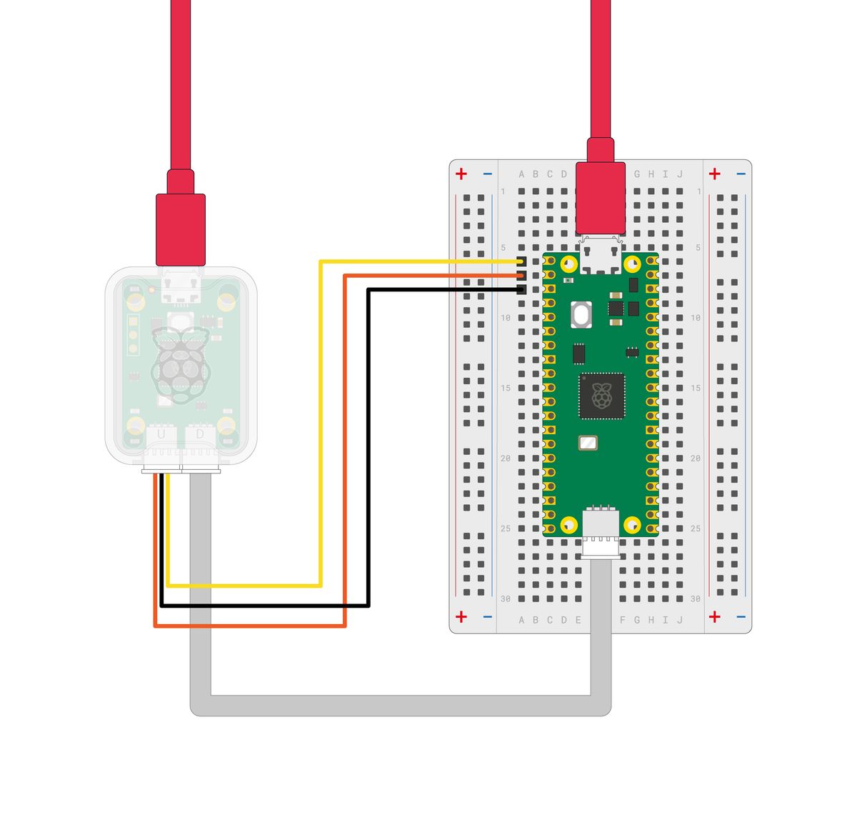
As you can see the inventory includes a debug probe. This was not in the initial parts list and is not fully required. An alternative approach, if you have another Pico, you can use it to act as a debug probe. This article shows how to configure that scenario. Since I am not experienced with programming a board like this I chose the easiest path, the debug probe linked in the inventory.
Setup Your Device
This will vary depending on whether you have a Pico H, Pico, or Pico W. In my case my Pico H did not have an SH connector or header pins on the debug locations so I soldered a three pin header in place. It appears there are a number of Pico H boards sold that do have this connector present. The Pico also already has an embedded LED however that may not be the case for other RP2040 boards. In this picture you can see the LED to the left below the screw hole. This still works if you wire your own LED with minor code tweaking. More on that later.
At this point, just plug the USB cables from the probe and from the Pico into your computer. Next, configuring the build tools.
Configure Build Tools
The fastest way to get started is with rp-rs which provides drivers for this board but also others as well. Fork this template and this will form the basis of your project. Navigate to the directory and lets proceed to configure our tooling.
First, add the thumbv6m target that will support our RP2040 with two Cortex-M0+ cores.
❯ rustup self update
info: checking for self-update
  rustup unchanged - 1.27.1

❯ rustup update stable
info: syncing channel updates for 'stable-x86_64-unknown-linux-gnu'

  stable-x86_64-unknown-linux-gnu unchanged - rustc 1.83.0 (90b35a623 2024-11-26)

info: checking for self-update

❯ rustup target add thumbv6m-none-eabi
info: downloading component 'rust-std' for 'thumbv6m-none-eabi'
info: installing component 'rust-std' for 'thumbv6m-none-eabi'
Next, if you don’t have systemd-devel installed it will need to be added.
❯ sudo zypper install systemd-devel
Loading repository data...
Reading installed packages...
Resolving package dependencies...

The following NEW package is going to be installed:
  systemd-devel

1 new package to install.

Package download size:   147.5 KiB

Package install size change:
              |     213.1 KiB  required by packages that will be installed
   213.1 KiB  |  -      0 B    released by packages that will be removed
With that installed, we can now install elf2uf2-rs to generate our build artifact.
❯ cargo install elf2uf2-rs --locked

    Updating crates.io index
  Installing elf2uf2-rs v2.1.1
  ...
  Compiling elf2uf2-rs v2.1.1
    Finished `release` profile [optimized] target(s) in 6.94s
  Installing /home/fr0bar/.cargo/bin/elf2uf2-rs
   Installed package `elf2uf2-rs v2.1.1` (executable `elf2uf2-rs`)
In order to support our debug probe we should also install probe-rs-tools
❯ cargo install --locked probe-rs-tools
    Updating crates.io index
  Downloaded probe-rs-tools v0.25.0
  Downloaded 1 crate (206.1 KB) in 0.89s
  ...
  Installing /home/fr0bar/.cargo/bin/probe-rs
   Installed package `probe-rs-tools v0.25.0` (executables `cargo-embed`, `cargo-flash`, `probe-rs`)
Now, if your two USB cables, one from debug probe and other from your Pico, are plugged into your computer you are ready to try and get your blinky lights. Lets run the build. The default stack seems insufficient to build the frunk_core dependency.
❯ RUST_MIN_STACK=16777216 cargo build
   Compiling frunk_core v0.4.3
   Compiling thiserror-impl v2.0.9
   Compiling cortex-m-rt-macros v0.7.5
   Compiling num_enum_derive v0.5.11
   Compiling proc-macro-error2 v2.0.1
   Compiling frunk_proc_macro_helpers v0.1.3
   Compiling frunk_derives v0.4.3
   Compiling cortex-m-rt v0.7.5
   Compiling rp2040-pac v0.6.0
   Compiling rp2040-hal-macros v0.1.0
   Compiling num_enum v0.5.11
   Compiling pio v0.2.1
   Compiling thiserror v2.0.9
   Compiling defmt-parser v0.4.1
   Compiling defmt-macros v0.4.0
   Compiling frunk v0.4.3
   Compiling defmt v0.3.10
   Compiling panic-probe v0.3.2
   Compiling defmt-rtt v0.4.1
   Compiling rp2040-hal v0.10.2
   Compiling rp-pico v0.9.0
   Compiling rp2040-project-template v0.1.0 (/home/fr0bar/Projects/rollyball)
    Finished `dev` profile [optimized + debuginfo] target(s) in 4.31s
❯ probe-rs list
The following debug probes were found:
[0]: Debug Probe (CMSIS-DAP) -- 2e8a:000c:E6633861A31A8838 (CMSIS-DAP)
One thing is likely missing for you still. Certainly on OpenSUSE you need to add some udev rules to make the debug probe reachable.
 ❯ sudo nano /etc/udev/rules.d/99-cmsis-dap.rules
 # Set the contents to this
 # SUBSYSTEM=="usb", ATTR{idVendor}=="2e8a", ATTR{idProduct}=="000c", MODE="0666", GROUP="plugdev"
 ❯ sudo nano /etc/udev/rules.d/99-debug-probes.rules
 # Set the contents to this
 # CMSIS-DAP
 # SUBSYSTEM=="usb", ATTR{idVendor}=="0d28", ATTR{idProduct}=="0204", MODE="0666"
 # J-Link
 # SUBSYSTEM=="usb", ATTR{idVendor}=="1366", ATTR{idProduct}=="0101", MODE="0666"
 # ST-Link
 # SUBSYSTEM=="usb", ATTR{idVendor}=="0483", ATTR{idProduct}=="3748", MODE="0666"
Now you can run it with the following command. You should see the LED blinking.
❯ cargo run
    Finished `dev` profile [optimized + debuginfo] target(s) in 0.03s
     Running `probe-rs run --chip RP2040 --protocol swd target/thumbv6m-none-eabi/debug/rp2040-project-template`
      Erasing ✔ 100% [####################]  12.00 KiB @  58.53 KiB/s (took 0s)
  Programming ✔ 100% [####################]  12.00 KiB @  22.64 KiB/s (took 1s)                 Finished in 0.53s
INFO  Program start
└─ rp2040_project_template::__cortex_m_rt_main @ src/main.rs:27
INFO  on!
└─ rp2040_project_template::__cortex_m_rt_main @ src/main.rs:68
INFO  off!
└─ rp2040_project_template::__cortex_m_rt_main @ src/main.rs:71
INFO  on!
└─ rp2040_project_template::__cortex_m_rt_main @ src/main.rs:68
INFO  off!
└─ rp2040_project_template::__cortex_m_rt_main @ src/main.rs:71
INFO  on!
└─ rp2040_project_template::__cortex_m_rt_main @ src/main.rs:68
INFO  off!
└─ rp2040_project_template::__cortex_m_rt_main @ src/main.rs:71
INFO  on!
└─ rp2040_project_template::__cortex_m_rt_main @ src/main.rs:68
#[entry]
fn main() -> ! {
info!("Program start");
let mut pac = pac::Peripherals::take().unwrap();
let core = pac::CorePeripherals::take().unwrap();
let mut watchdog = Watchdog::new(pac.WATCHDOG);
let sio = Sio::new(pac.SIO);
// External high-speed crystal on the pico board is 12Mhz
let external_xtal_freq_hz = 12_000_000u32;
let clocks = init_clocks_and_plls(
external_xtal_freq_hz,
pac.XOSC,
pac.CLOCKS,
pac.PLL_SYS,
pac.PLL_USB,
&mut pac.RESETS,
&mut watchdog,
)
.ok()
.unwrap();
let mut delay = cortex_m::delay::Delay::new(core.SYST, clocks.system_clock.freq().to_Hz());
let pins = bsp::Pins::new(
pac.IO_BANK0,
pac.PADS_BANK0,
sio.gpio_bank0,
&mut pac.RESETS,
);
// This is the correct pin on the Raspberry Pico board. On other boards, even if they have an
// on-board LED, it might need to be changed.
//
// Notably, on the Pico W, the LED is not connected to any of the RP2040 GPIOs but to the cyw43 module instead.
// One way to do that is by using [embassy](https://github.com/embassy-rs/embassy/blob/main/examples/rp/src/bin/wifi_blinky.rs)
//
// If you have a Pico W and want to toggle a LED with a simple GPIO output pin, you can connect an external
// LED to one of the GPIO pins, and reference that pin here. Don't forget adding an appropriate resistor
// in series with the LED.
let mut led_pin = pins.led.into_push_pull_output();
loop {
info!("on!");
led_pin.set_high().unwrap();
delay.delay_ms(500);
info!("off!");
led_pin.set_low().unwrap();
delay.delay_ms(500);
}
}
If you aren’t using a Pico with an embedded LED it’s not that bad. As you see the program is toggling led_pin to cause the LED to flash. On the Pico H this is GPIO25. If you didn’t have a built in LED you could change this to let mut led_pin = pins.gpio5.into_push_pull_output(); for instance if you want to flash your LED on pin 5.
But that’s it. Particularly simple. Next I will be looking to wire up my Pixart chip and output the deltas of X/Y. If I am lucky I will also be able to sample the sensitivity and resolution on those numbers. Until then, merry Christmas.